(China (Mainland))


Product Summary
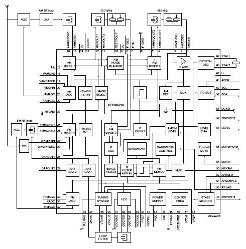
The TEF6862HL/V1S/S422 is a single-chip car radio tuner for AM, FM and weather band reception providing AM double conversion for LW, MW and full range SW (11 m to 120 m bands) with IF1 = 10.7 MHz and IF2 = 450 kHz. FM double conversion to IF1 = 10.7 MHz and IF2 = 450 kHz with integrated image rejection for both IF1 and IF2; integrated IF filter with variable bandwidth and automatic bandwidth control algorithm with flexibility via the I2C-bus; capable of US FM, Europe FM, Japan FM, East Europe FM and weather band reception; all FM bands can be selected using high injection LO or low injection LO in the FM mixer 1. Tuning system of the TEF6862HL/V1S/S422 including crystal oscillator, VCO, PLL synthesizer and state machine for timing uncritical control of search, preset change and AF check via microcontroller.
Parametrics
TEF6862HL/V1S/S422 absolute maximum ratings: (1)VCCA analog supply voltage: 8V to 9V; (2)ICC(tot) total supply current(Current in FM mode): 101.9mA; (3)ICC(tot) total supply current(Current in AM mode): 84.4mA; (4)ttune tuning time(Europe FM and US FM band; fref = 100 kHz; fRF = 87.5 MHz to 108 MHz): 1ms; (5)ttune tuning time(AM MW band; fref = 20 kHz; fRF = 0.53 MHz to 1.7 MHz): 10ms; (6)tupd(AF) AF update time(cycle time for inaudible AF update; (7)including 1 ms mute start and 1 ms mute release time): 6.5ms.
Features
TEF6862HL/V1S/S422 features: (1)High dynamic range FM front-end mixer for conversion of FM RF (65 MHz to 108 MHz and USA weather band) to an IF frequency of 10.7 MHz; mixer provides inherent image rejection which can be switched from low injection LO to high injection LO via the I2C-bus; (2)FM front-end AGC PIN diode drive circuit; AGC detection at the FM font-end mixer input and the IF filter input; AGC threshold for detection at the mixer input is programmable and keyed AGC function can be selected via the I2C-bus; the AGC PIN diode drive can be activated by the I2C-bus for a search tuning in local mode; in AM mode the AGC PIN diode drive can be activated by the I2C-bus if required; information on amount of PIN diode AGC is available via the I2C-bus; (3)FM front-end mixer includes +6 dB gain setting via the I2C-bus; (4)FM second mixer for conversion of IF1 10.7 MHz to IF2 450 kHz including inherent image rejection; the gain can be controlled via the I2C-bus; (5)Integrated FM channel selection filter with continuous variable bandwidth providing simultaneous low distortion and high selectivity with only one external ceramic filter; improved sensitivity with dynamic threshold extension can be enabled via the I2C-bus; (6)Fully integrated FM demodulator with very low distortion; (7)Digital bandwidth control algorithm with detection on adjacent channel information, deviation, detuning and level with customer flexibility via the I2C-bus; (8)Digital alignment circuit for bus controlled adjustment of oscillator tuning voltage to two FM antenna tank circuit tuning voltages; AM and FM level start and slope alignment; IF filter and demodulator center frequency alignment; (9)AM and FM level detection (signal strength indication); (10)Separate RF input to FM front-end mixer for weather band; (11)Flag or voltage output indicators for actual IF bandwidth information; (12)AM front-end mixer for conversion of AM RF to an IF frequency of 10.7 MHz; (13)AM RF AGC circuit for external cascode AGC and PIN diode AGC; (14)AM noise blanker with detection at IF1 and blanking at IF2; (15)AM second mixer for conversion of IF1 10.7 MHz to IF2 450 kHz; IF2 AGC amplifier and AM demodulator with low distortion; (16)For AM stereo applications the gain controlled AM IF2 output voltage can be switched to MPXAM output pin via the I2C-bus; (17)Crystal oscillator providing frequency for second conversion, references for synthesizer PLL and analog signal processor and timing for tuning action; (18)LC tuning oscillator with low phase noise and oscillator dividers with selectable divider ratios for worldwide tuner reception without band switching in application; (19)Fast synthesizer PLL tuning system with dynamically adapting loop parameters combining fast PLL frequency jumps for inaudible RDS updating with low spurious responses for large signal-to-noise ratios; (20)Sequential state machine for preset change, search and inaudible AFU allowing a timing uncritical microcontroller operation; the state machine generates timing signals for the internal inaudible tuning mute and analog or digital signal processor; (21)An alternative frequency check can be initiated by the signal processor for audio correlation algorithms directly without involvement of the microcontroller; (22)Audio soft slope tuning mute circuit allowing inaudible AFU; (23)Two hardware programmable I2C-bus addresses; (24)Two software controlled flag outputs; (25)Several test modes for fast IC and system tests.
Diagrams
 |
 TEF6601T/V5,512 |
NXP Semiconductors |
Tuners 100MHz 8.5V |
Data Sheet |
|
|
||||||||||||
|
TEF6601T/V5,518 |
NXP Semiconductors |
Tuners 100MHz 8.5V |
Data Sheet |
|
|
||||||||||||
 |
TEF6606T/V5,512 |
NXP Semiconductors |
Tuners RF TRANSCEIVER |
Data Sheet |
|
|
||||||||||||
|
TEF6606T/V5,518 |
NXP Semiconductors |
Tuners RF TRANSCEIVER |
Data Sheet |
|
|
||||||||||||
|
TEF6607T/V5,512 |
NXP Semiconductors |
Tuners Power Interface |
Data Sheet |
|
|
||||||||||||
|
TEF6607T/V5,518 |
NXP Semiconductors |
Tuners Power Interface |
Data Sheet |
|
|
||||||||||||